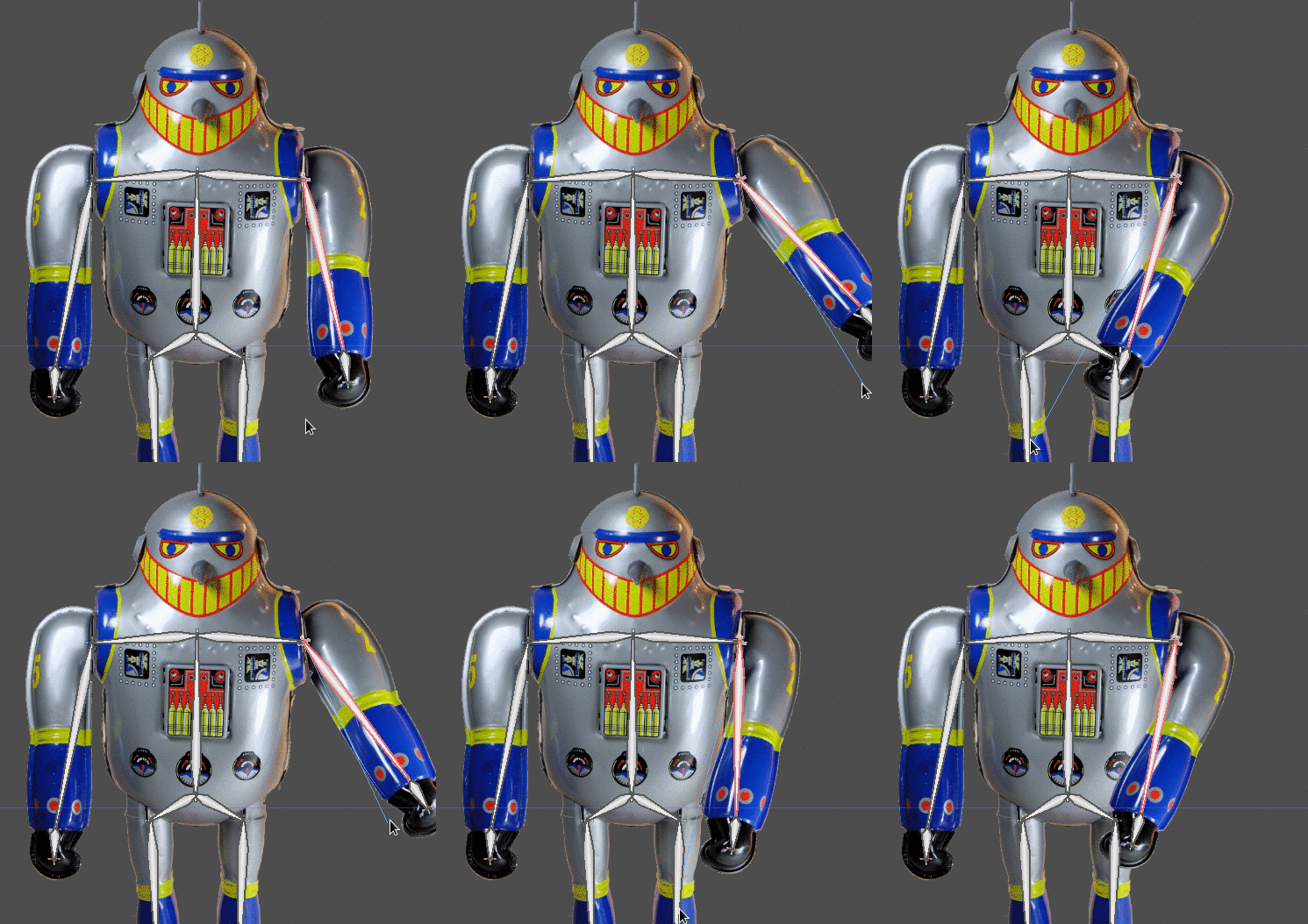
Currently, Godot is pretty comfortable for doing 2D cutout animation, with several games in development making use of this feature.
A very common request, though, was the ability to do custom mesh deformation based on the same bones used to animate separate parts. This would allow deforming such parts, for a more organic animation feel.
This was recently added to GitHub head and, while overall 2D editing is a bit unstable right now (due to a massive reorganization of the 2D editor), it will be soon be possible to fully make use of this feature.
As always, please remember Godot is made out of love, so please consider becoming our patron!
How it works
Two new types of nodes were added: Skeleton2D and Bone2D. The former is the reference skeleton (much similar to the existing Skeleton node for 3D), while the later is actually used to build a bone hierarchy on top of it:
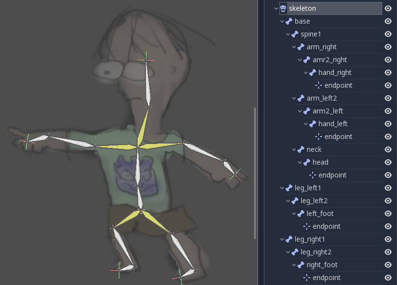
For editing, the workflow is the same as cutout, bones are laid out in a tree then marked as visual bones for editing (they are not visible by default). This is a bit more of a hassle than with dedicated software, but fortunately the process is done only once.
Of course, compared to dedicated software, this workflow has the huge advantage that nodes are fully accessible within the engine, allowing to mix them up with particles, shaders, other nodes (i.e. swap a sword), and other visual effects built-in to Godot.
Using with MeshInstance2D
Although the recently added MeshInstance2D node now supports skeletal deforms, it can’t be created with such property within the editor.
This allows, however for the community to write importers for tools such as Spine or CoaTools that become actual Godot scenes instead of an opaque node.
Using with Polygon2D
The Polygon2D node has gained many new features to make working with skeletons easier. Here’s a short tutorial on how to use it:
Note: This tutorial is already outdated, endpoints are no longer required and bone editing creates visible bones automatically now, thus making working with skeletons in Godot as easy as in any other software.
1-Draw a polygon outline around the image:
Normally for 2D animation, it’s still more convenient to split the object into parts and then use bones on specific parts of them (as they handle overlap better) so actual use of this feature will be more of an extension to the existing cutout workflow. Still, for brevity, this tutorial will show how to do it on a single object.
Create a Polygon2D node, then immediately assign an image to it (otherwise UV editing won’t open).
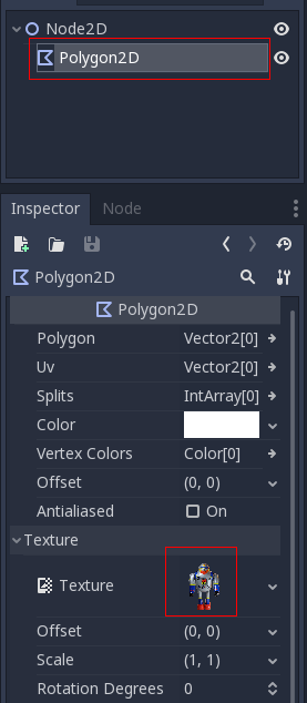
Open the UV editing window (again, without an image assigned, this won’t open)

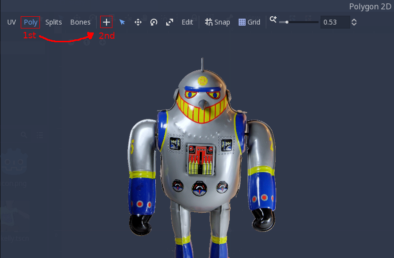
Once open, go to the newly added Polygon section of he editor. Once there, click the + button to add points.
Draw a close polygon outline around the object:
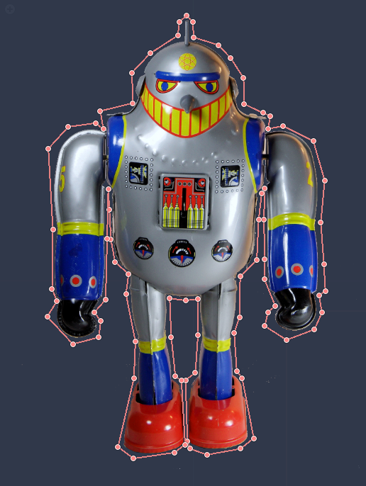
Finally, this will become your actual polygon when editing the scene:
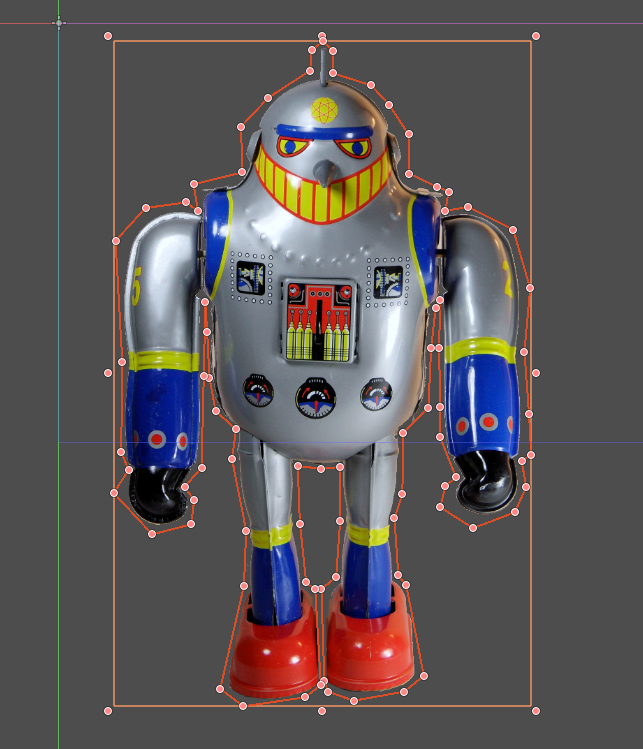
2-Create a skeleton to match the polygon
Starting from a Skeleton2D, add a hierarchy of Bone2D nodes to match the desired skeleton. Remember that each Bone2D must be placed where the bone Starts. To have a reference where the hierearchy ends, just add a Position2D node at the end.
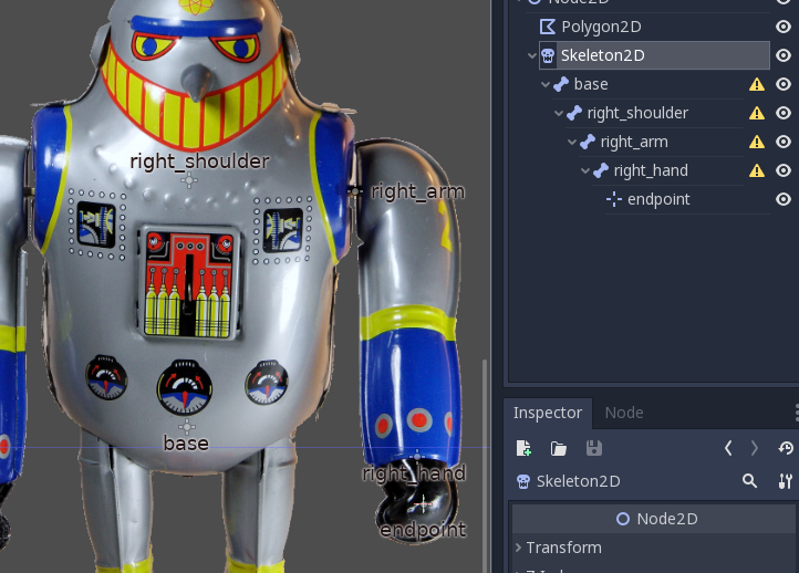
Once you have a chain of bones, you can make them visible in the Bone menu. Just select all bones (except the base, as this acts on a node towards the parent node), and create visual bones:
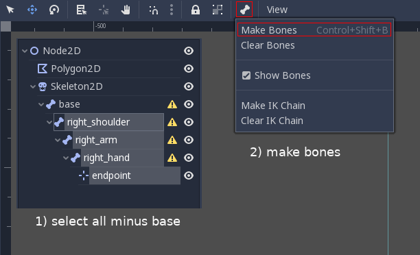
They will now appear visually and can be manipulated more easily, including setting up IK chains:
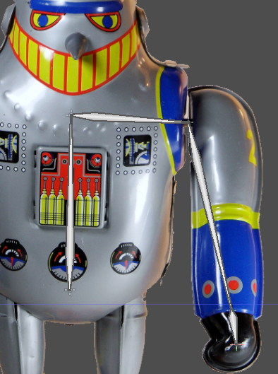
Repeat this process to have a full skeleton. For skeleton points where two bones emerge (as in, the base position for left and right shoulders), having them both in the same position is fine. In fact, in this example, base, left_hip and right_hip share the position and hierarchy level as 3 root bones.
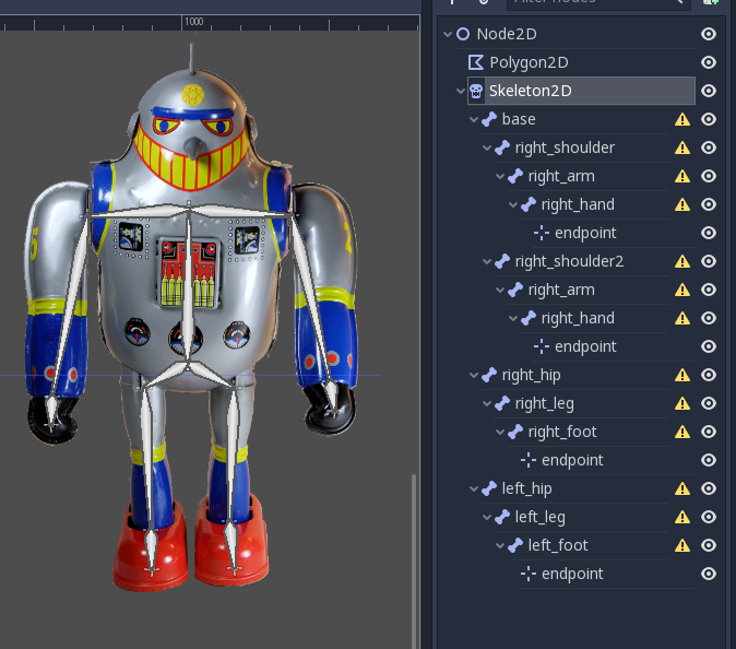
Ok, skeleton is complete! You might have noticed that nodes are showing warnings. This is because they need a rest pose. This is the default reference pose for the skeleton, and it must exist before bones are animated (so Godot knows how to rotate or move the points based on how rotated the or moved the bones is).
Create the rest pose (once the skeleton is complete) by selecting the Skeleton2D node and the Skeleton menu:

3-Create splits to improve triangulation
As polygons are converted to triangles for drawing internally, this process may need some help in order to created less unexpected deformations. Select the Polygon2D node and enter the UV menu again. This time go to the Splits mode. From there, to the Add Split mode:

Finally, connect sets of two points near bone unions, indicating that you dont want triangles to be generated across such splits:
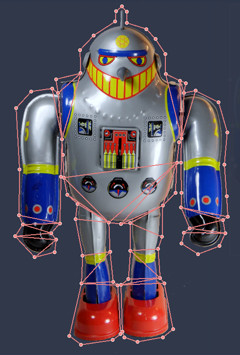
This process may demand some trial an error, as for complex polygons it may need to be re-adjusted a bit after the process is done.
4-Setup polygon for painting
Exit the UV editor and re-select the Polygon2D node. From there go to the Skeleton property. Assign the Skeleton2D node to it.
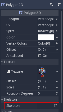
Go back to the UV editor and select the Bones section, and from there the Paint mode:

While the skeleton is visible over the image now, the bones are still not available for painting.
The Polygon2D node needs to store bone painting information. To create this, push the “Sync Bones to Polygon” button. If you later add, remove or reparent nodes, you will need to push this button again. This will ensure that the minimum possible paint information is lost each time the skeleton hierarchy is modified.
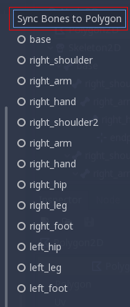
5-Painting bone weights
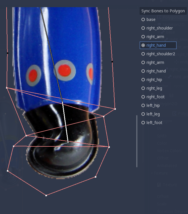
Everything is now ready for weight painting!! Now select bones fromt he list, and paint the area they affect. When a point is fully white, it’s fully affected by the bone. When black, it’s not affected at all.
A point may be affected by multiple bones. When this happens, the bone will try to satisfy both bones as best as possible, by averaging their influence. This makes deformation look soft.
Here are some examples on how weights are painted for different bones:
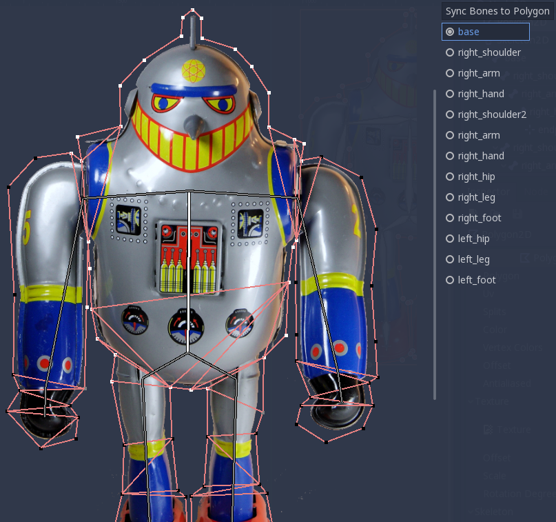
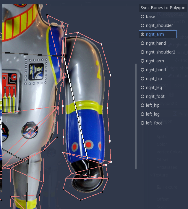
6-Animate!!
Now have fun animating deformable polygons!
